|
Weld Line Prediction: From Injection Molding Simulation to Structural Simulation
4/11/2012 |
|
|
With aid of the interface SIGMAlink, the weld lines predicted with the injection molding simulation software SIGMASOFT® can now be mapped into Finite Element Analysis Software and be considered in the structural design of injection molded parts.
Schaumburg, IL, April 1st 2012 - SIGMA Plastic Services, Inc., Schaumburg, IL, presents a new functionality of its injection molding simulation software SIGMASOFT®. The simulation of the cavity filling in injection molding allows identifying regions where weld lines are formed, not only on the surface but also through the part's thickness, with a complete 3D approach. With the interface SIGMAlink it is now possible to transfer this 3D information into FEA (Finite Element Analysis) software, to consider the drop in mechanical properties in these regions when performing structural design analysis. A particular advantage of SIGMASOFT® is the 3-dimenional prediction of the weld lines, which reproduces the weld regions not only on the surface, but also through the part's thickness - as it occurs in reality.
Weld lines occur as a consequence of the collision of two (or more) flow fronts in the cavity of a mold. This disruption in the homogeneity of the injection molded part causes optical defects, which compromises the surface quality, but also produces a weakening from the mechanical point of view and, under certain circumstances, weld lines can even act as stress intensifiers. Therefore, there is a loss in the mechanical properties in the regions where weld lines appear.
Using the "tracer" technology, which has been available for years in SIGMASOFT®, the appearance of weld lines can be reproduced during the filling stage. The location of the weld lines can be described precisely and additionally an indication is given on how critical they are. The formation of the weld lines during the filling stage and the way they flow as the packing pressure is applied are predicted 3-dimensionally.
The interface SIGMAlink enables exporting (mapping) physical and flow-related properties into commercial software for FEA (such as Ansys, Abaqus, Radios, etc.). Factors such as flow and thermally induced stresses and fiber orientation can be considered in the FEA. With the further expansion of SIGMAlink it is now possible to export information regarding the final position and 3D-profile of the weld lines into the structural FEA. In this way, the drop in the mechanical properties produced by weld lines can also be considered in the mechanical part design.
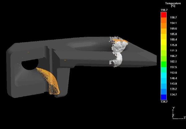
In Figure 1 the formation of a weld line region in SIGMASOFT® is presented. The flow front is depicted in grey. The "tracer" particles in orange show clearly that the melt fronts do not collide in a flat region, but that this weld line has a complex 3D profile at the end of the filling and packaging phases.
Caption
Figure 1 - The tracer technology in SIGMASOFT® allows visualizing the fully 3D profile of weld lines over the part thickness. With SIGMAlink this information can now be mapped into structural FEA.
|
|
|
|
|
|
主站蜘蛛池模板:
亚洲AV人无码激艳猛片|
自慰无码一区二区三区|
日韩国产欧美精品在线|
成人肏屄视频|
岛国中文字幕一区二区|
久久久久久久人妻无码中文字幕爆|
无码精品国产D在线观看|
又湿又紧又大又爽a视频|
日逼av|
完整在线视频免费黄片|
蜜臂av|
日本一区二区a√成人片|
国产sm调教折磨视频|
午夜AAAAA级岛国福利在线|
少妇人妻无码专区视频|
成人福利国产午夜AV免费不卡在线
|
亚洲欧美综合一区二区三区|
www.色色色.com|
亚洲无码av另类本色|
亚洲高清国产拍精品网络战|
日本一区二区精品色超碰|
亚洲综合无码AV在线观看|
国产精品自拍自在自线|
天天爱天天做天天爽夜夜揉
|
丝袜人妻无码专区视频|
午夜福利二区无码在线|
中文字幕va一区二区三区|
欧美和黑人xxxx猛交视频|
少妇被粗大的猛烈进出动视频|
亚洲欧洲精品成人久久曰不卡|
又长又粗又爽又高潮的视频|
免费av网站|
正蓝旗|
无码人妻久久一区二区三区蜜桃
|
人妻少妇久久中文字幕|
国产精品线在线精品|
亚洲综合网中文字幕在线|
www.rihanav|
国产超爽精品国语对白|
亚洲aⅴ男人的天堂在线观看
|
日韩精品欧美激情亚洲综合|